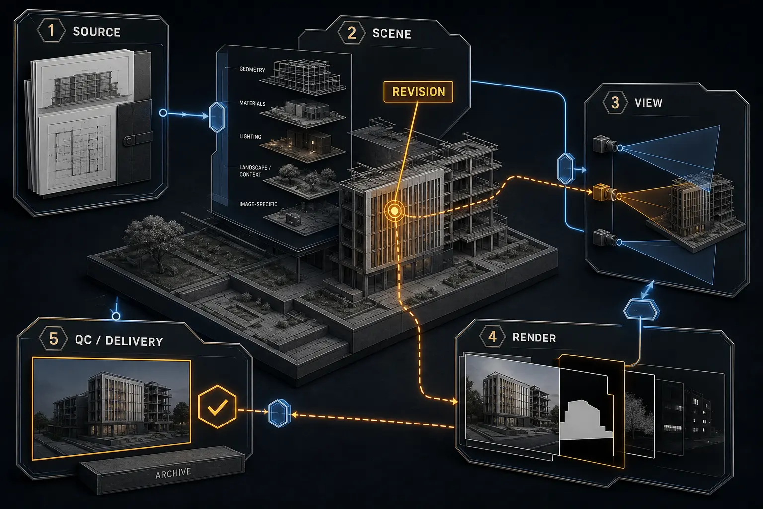
An architectural visualization workflow is the coordinated production process connecting source information, scene construction, image-making, review, revision, and delivery. A reliable workflow does more than produce an attractive render: it controls dependencies and detects changes before they propagate through geometry, cameras, materials, lighting, rendering, and post-production.
The practical difficulty is that architectural inputs rarely remain static. Design information evolves, unresolved details become visible, and feedback often combines architectural changes with visual preferences. A late revision can invalidate several stages at once. The solution is not a rigid sequence but a pipeline with clear inputs, deliberate checkpoints, traceable decisions, and enough structure to absorb change without losing design fidelity or image consistency.
Table of Contents
- The Stages of an Architectural Visualization Workflow
- Project Intake and a Reliable Scene Foundation
- Developing Cameras, Materials, and Lighting in the Right Order
- Rendering and Post-Production Without Losing Control
- Managing Reviews and Revisions
- Quality Control and Final Delivery
- FAQ
- What to Do Next?
The Stages of an Architectural Visualization Workflow
A professional architectural visualization workflow usually covers brief validation, source-file assessment, geometry preparation, camera development, materials and lighting, test rendering, post-production, review, revision, quality control, delivery, and archiving. These are not isolated artistic tasks. They form an architectural visualization pipeline in which the output of one stage becomes the input to another.
The useful distinction is not simply between unfinished and finished work. Production moves through three conditions: exploratory, approved, and production-ready. Exploratory work tests possibilities cheaply. An approved decision has been reviewed and is stable enough for dependent work to proceed. Production-ready work has also passed the technical checks required for final output. A camera may be compositionally approved, for example, while the scene visible through it still contains unresolved geometry.
Approvals are checkpoints, not promises that nothing will change. Their purpose is to make the cost and consequences of change visible. If a camera has been approved before detailed look development, a later request to replace it can be identified as more than a minor framing adjustment: it may expose new geometry, require additional assets, alter the lighting hierarchy, and invalidate existing post-production.
In practice, stages overlap. Materials may be tested while geometry is still being refined, and lighting studies may reveal problems with camera placement. That flexibility is useful, but critical dependencies still need an intentional order. High-impact choices should be tested with inexpensive outputs before detailed assets, high-resolution renders, or labor-intensive compositing depend on them.
Consider a late facade change. In an unstructured project, it may be noticed only after final rendering and detailed retouching. The revised facade then changes visible joints, reflections, shadows, interior visibility, object masks, and painted corrections. In a controlled visualization production workflow, the change is traced through the approved cameras and affected image components before work begins. Iteration still happens, but it becomes controlled propagation rather than accidental rework.
Project Intake and a Reliable Scene Foundation
A reliable architectural rendering workflow begins before image-making. The intake package should establish the current drawings or model files, revision identifiers, project scope, required views, image proportions, output dimensions, intended use, reference imagery, material information, landscape expectations, deadlines, and review responsibilities. Unresolved items should be recorded rather than quietly filled with assumptions.
An authoritative source should be identified for each type of design information. A model, drawing set, material schedule, and marked-up image may disagree. Without a defined hierarchy, an artist can produce something visually plausible but architecturally incorrect. Ambiguity should be raised early, especially where it affects visible geometry, facade rhythm, material boundaries, landscape levels, or interior content.
Imported geometry should be assessed, not assumed to be render-ready. Common problems include incorrect units, duplicate surfaces, reversed normals, open edges, placeholder glazing, excessive detail, missing junctions, and deeply nested hierarchies. Coordinate systems and scale must be verified before cameras, assets, or simulations depend on them.
Scene organization determines how safely the project can change. Architecture, landscape, furniture, lighting, contextual elements, and image-specific additions should remain separable. Clear naming and hierarchy make material assignment, visibility control, asset replacement, and troubleshooting more predictable. Instancing reduces unnecessary duplication, while linked or referenced assets allow repeated components to be updated without destructive editing. The exact structure depends on the software and team, but the principle is stable: a component should be replaceable without dismantling unrelated work.
Suppose a supplied design model contains duplicate facade surfaces, temporary glass, unjoined cladding panels, and furniture embedded in the same hierarchy as the building. If production begins immediately, material assignments may attach to unstable objects, and furniture replacement may disturb architectural geometry. An intake check separates those systems, records unresolved facade conditions, verifies scale, and creates clear revision boundaries.
Geometry simplification is legitimate when it removes invisible detail, improves render performance, or replaces needlessly complex assets without changing the image. It becomes risky when it alters silhouettes, junctions, panel depth, shadow behavior, or other evidence of design intent. A well-organized CGI production pipeline makes simplification deliberate rather than an accidental loss of architectural information.
Developing Cameras, Materials, and Lighting in the Right Order
Camera development should begin early because viewpoint, focal length, horizon, framing, and image proportions determine which parts of the project matter most. The camera also defines how much modeling and dressing the image requires. A view that reveals the rear context, roofscape, or interior through glazing can expand scope significantly, even if the requested deliverable is still described as one image.
Clay renders and low-cost previews are valuable because they isolate composition from surface detail. They allow several views to be compared before materials and final lighting make a weak camera appear more convincing than it is. Camera approval stabilizes the archviz workflow, but it should not become an inflexible lock. Lighting tests or later design information may justify a measured adjustment.
Once the strongest view is selected, material development can concentrate on what the camera reveals. Material quality depends on scale, reflectance, roughness, texture direction, edge response, and controlled variation. A physically plausible material can still communicate the wrong architecture if its texture scale misrepresents panel dimensions or its reflections obscure an important facade rhythm.
Lighting is both spatial communication and composition. Daylight direction establishes form, depth, and shadow hierarchy. Artificial lighting affects focus, occupancy, and the balance between interiors and exteriors. Exposure and contrast should preserve legibility in the areas that carry the design idea rather than giving every surface equal visual weight.
Materials and lighting must be evaluated together because appearance is relational. Glazing changes with reflected context and interior brightness. Rough stone can appear flat under broad frontal illumination but reveal its character under grazing light. Dark metal may read as black, colored, or reflective depending on its environment. Material approval without representative lighting is therefore incomplete.
For an exterior dusk image, a sound 3D rendering workflow might test several compositions with neutral materials, approve the most informative view, resolve facade and glazing behavior, then establish the interior-exterior lighting balance. Fully texturing the entire project before selecting the camera can commit effort to surfaces that may never appear and can make composition changes more expensive.
Rendering and Post-Production Without Losing Control
Rendering should progress from fast previews to representative tests and only then to final-resolution output. A useful test render must represent the conditions that affect the final image: camera dimensions, color management, major assets, lighting balance, material response, and enough quality to expose artifacts. A preview that conceals noise, displacement problems, or reflection issues is cheap but not informative.
Before committing to a final render, confirm output dimensions, aspect ratio, asset availability, quality settings, render-time risks, and any image-set consistency requirements. Representative crops can test difficult regions such as glazing, vegetation, fine facade patterns, indirect interior light, or depth of field. Higher settings cannot repair weak geometry, incorrect material scale, or poor lighting logic.
Render passes and masks are most useful when they preserve options the project is likely to need. They can support selective color correction, object isolation, atmospheric depth, and controlled compositing. There is no universal pass list. Outputs should correspond to actual revision boundaries; generating many unused passes adds storage and complexity without necessarily adding control.
Post-production is controlled image finishing, not a place to conceal unresolved scene problems. It can shape tonal hierarchy, atmosphere, entourage, vegetation integration, local contrast, and color relationships. Non-destructive organization should preserve the connection between source renders, masks, composited elements, and final output so a revised render can be inserted without rebuilding the image from scratch.
The boundary between 3D and post-production depends on how an issue behaves. Geometry, perspective-dependent elements, repeated structural problems, major material behavior, and lighting relationships usually belong in the scene. Local tonal refinements, atmospheric depth, edge integration, and image-specific finishing can often be handled safely in post-production. If a correction must remain consistent across several cameras, fixing it at the source is usually more reliable.
If a facade appears too flat in a test render, painting contrast over it should not be the first response. The cause may be insufficient panel depth, uniform roughness, frontal lighting, weak reflections, or compressed exposure. Diagnosing the cause preserves architectural logic. Painting over the symptom may create an attractive patch that fails on the next view or disappears when the facade is rerendered.
Managing Reviews and Revisions
Revision resilience must be designed into the architectural visualization workflow. Feedback should first be classified as a design revision, visual-direction revision, technical correction, content change, or preference-based adjustment. These categories can arrive in the same marked-up image, but they have different consequences and should not be treated as equivalent editing requests.
A design revision changes the represented architecture. Visual-direction feedback changes mood, composition, emphasis, or image character. A technical correction addresses an error such as a broken texture, render artifact, or incorrect output. Content changes add, remove, or replace elements such as furniture, planting, or people. Preference-based feedback adjusts choices that may be valid but are not favored, such as entourage density or sky character.
Review rounds should use identifiable image versions, consolidated comments, and annotations precise enough to locate each requested change. Decision ownership also matters: contradictory instructions should be resolved before execution, and superseded comments should be explicitly marked. This need not become bureaucratic. A short change log can be enough if it records what changed, which instruction is current, and which views are affected.
Before executing a revision, perform an impact assessment. Trace the request through geometry, cameras, materials, lighting, rendering, masks, and post-production layers. A request to enlarge a window is not merely an image edit. It may alter facade geometry, reveal more of the interior, change reflected context, increase daylight penetration, move shadows, expose unfinished assets, and invalidate existing masks or retouching.
The impact assessment determines the lowest-cost reliable validation step. A geometry change may first require viewport captures or low-resolution renders from all affected cameras. A mood adjustment may need a representative lighting test rather than a complete image set. Expensive rerenders should follow confirmation that the underlying revision is correct, not serve as the first proof that it was interpreted properly.
Every revision also needs a regression check. Confirm that the requested change has not damaged previously approved composition, material continuity, lighting balance, reflections, object visibility, masks, or consistency across the set. Regression checking is easy to overlook because attention naturally focuses on the marked area. Production failures often appear elsewhere, where a shared asset or scene-level adjustment has changed an image that was not meant to change.
Quality Control and Final Delivery
Final quality control should be divided into architectural, visual, technical, and delivery checks. These categories catch different failures. An image can be polished but architecturally wrong, faithful to the model but visually unclear, visually convincing but technically unsuitable, or correct in every other respect while being based on an obsolete revision.
Architectural checks compare the images with current design information. Verify visible geometry, facade logic, junctions, material boundaries, scale, landscape levels, requested content, and any areas raised during review. Visual plausibility is not enough where design fidelity matters. A plausible parapet, mullion, or cladding joint is still incorrect if it contradicts the approved design.
Visual checks cover composition, hierarchy, lighting continuity, reflections, edge quality, repeated assets, entourage integration, vegetation, and image-set consistency. Multiple deliverables should be viewed together. In a three-image set, individually successful frames may still conflict through different sky treatments, color balance, material character, vegetation density, or contrast levels.
Technical checks confirm pixel dimensions, aspect ratio, color space, file format, compression, naming, and visible artifacts. Inspect outputs at their intended delivery size rather than relying only on a magnified working file. Look for noise, halos, broken masks, banding, clipped highlights, unintended sharpening, missing textures, and small compositing errors that become obvious in the final output.
Delivery checks verify that the approved version is being sent, all expected files are present, naming is unambiguous, and no working marks or obsolete alternatives remain. The delivered files should correspond exactly to the reviewed outputs. Last-minute conversions or renaming can introduce mistakes after visual approval has already occurred.
The architectural visualization pipeline should end with a retrievable production record. Archive the scene, source renders, linked dependencies, essential textures, compositing files, review notes, and a record of the delivered version. Archiving does not assume the project will never change again. It makes a future update possible without reconstructing the production history from incomplete files.
FAQ
How long does an architectural visualization workflow take?
Duration depends on scope, number of views, source-model condition, design maturity, asset requirements, output resolution, approval speed, and revision volume. Image count alone is not a reliable measure. A single view with unresolved design inputs and extensive custom content can carry more production risk than several views from a stable, organized scene.
When should camera views be approved?
Initial camera views should usually be approved before detailed material work and final lighting, using clay renders or other low-cost previews. Approval stabilizes composition and visible scope, but it should still allow justified adjustments when lighting tests, design revisions, or newly resolved information affect the image.
What should be fixed in 3D, and what belongs in post-production?
Fix geometry, perspective-dependent elements, repeated structural issues, major lighting relationships, and material behavior at the source. Use post-production for controlled tonal refinement, atmosphere, compositing, integration, and localized finishing when those changes remain consistent and editable. If the same correction is needed across several views, it generally belongs in 3D.
How do you control late design revisions?
Classify the change, identify affected views and dependencies, update version records, and validate the revision with low-cost outputs before final rendering. Selective rerendering may be appropriate when reliable masks and source relationships exist. Finish with regression checks to ensure the change has not damaged previously approved areas. The goal is controlled propagation, not the elimination of late changes.
What is the difference between a workflow and a checklist?
A checklist verifies expected conditions. A workflow defines stages, inputs, outputs, dependencies, responsibilities, review points, and responses to change. Checklists are valuable within a larger production system, particularly for intake, render readiness, quality control, and delivery, but they do not explain what should happen when a dependency changes.
What to Do Next?
Map the production sequence used on one visualization project. For each stage, document its inputs, expected output, responsible decision, and the conditions that must be stable before downstream work begins. Then identify the failure points that produce the most rework, whether they involve unclear source files, premature material development, fragmented feedback, or weak final checks.
Create a simple revision-impact check covering geometry, cameras, materials, lighting, rendering, and post-production. Add separate architectural, visual, technical, and delivery quality checks, then test the workflow through one production cycle. Revise the process around actual exceptions and bottlenecks rather than imposing one universal template on every project.